Introduction
The prevalent trend to adopt large area PhotoMultiplier Tubes (PMT), typically with a diameter of 20 inch, has to take into account the non-linear reconstruction of the deposited charge, when a single PMT collects an enough amount of electromagnetic energy to produce more than a single PhotoElectron (PE). This pile up effect is accentuated in the large detector, where the size is comparable to the LS attenuation length. In fact, an highly non-uniform detector response is expected, enhancing pile up at the single PMT level for events happening close to the detector edges. The large acceptance of PMT threatens the time reconstruction of the event and hence of fiducial volume, which is often mandatory to reject background from natural radioactivity. Such fiducialisation relies on the capability to precisely reconstruct the event vertex position, which in turns demands a precise time information. Finally because of the large number of channels, budget constrains often force the PMT readout to take place on the same cable used to supply the high voltage (AC coupling), hence distorting the PMT output waveform.
In a standard 20 inch PMT, for an event of reactor antineutrino in some tens kton detector, more than 50 % of the total charge is collected by more than 1 PE. Although an high frequency sampling of the PMT output waveform provided by Flash Analog-to-Digital Converters (FADCs) improves the calorimetric performance of the detector, an accurate analysis of the digital signal is mandatory for an unbiased reconstruction of input charge and of the photon time of arrival.
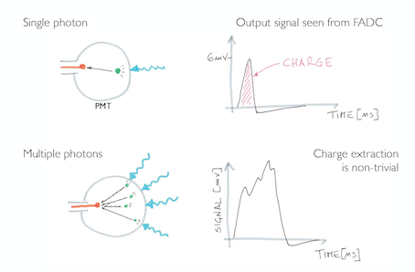
Figure 1: Sketch illustrating of the bias on charge recontruction due to multi-hit on a PMT
The main purpose of the presented algorithm is to reduce the bias on the reconstructed charge due to the previously described hardware effects.
We present three different algorithms. The first is used to analyze the input file with Digital Signal Processing technique as filtering and deconvolution (Deconvolution Algorithm - DA) and reconstruct the charge (Integration Algorithm - IA), the second is used to generate the SPE shape as input for the first algorithm, while the third is used to generate events in order to validate the first one (Event Building).
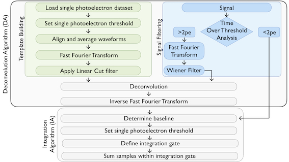
Figure 2: Flow Diagram of the Charge Recontruction Algorithm (CRA)
The algorithms can be downloaded at this link.