In fig. ![[*]](crossref.png) a sketched view of the scientific payload
shows how the various instruments are placed.
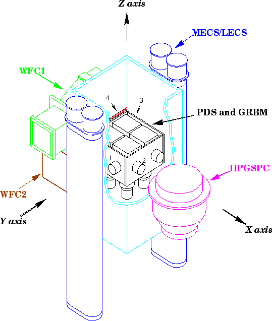
a sketched view of the scientific payload
shows how the various instruments are placed.
The instruments are grouped into two classes: the Narrow Field
Instruments (NFIs) and the Wide Field Cameras (WFCs).
All the NFIs are co-aligned and pointing along the positive
direction of the Z axis of the BeppoSAX frame
of reference; they consist of the following (Table ):
a LECS (Low Energy Concentrator Spectrometer, ![]() keV),
three MECS (Medium Energy Concentrator Spectrometers,
keV),
three MECS (Medium Energy Concentrator Spectrometers, ![]() keV),
a HPGSPC (High Pressure Gas Scintillation Proportional Counter,
keV),
a HPGSPC (High Pressure Gas Scintillation Proportional Counter,
![]() keV), and a PDS (Phoswich Detection System,
keV), and a PDS (Phoswich Detection System, ![]() keV).
Each imaging GSPC is located at the focal plane of an X-ray
concentrator system.
The WFCs (
keV).
Each imaging GSPC is located at the focal plane of an X-ray
concentrator system.
The WFCs (![]() keV) consist of two identical coded mask cameras
co-aligned with the Y axis: WFC1 points along the negative
direction and WFC2 along the positive one.
keV) consist of two identical coded mask cameras
co-aligned with the Y axis: WFC1 points along the negative
direction and WFC2 along the positive one.
Eventually, there is another instrument which, on principle, has
no imaging capability: the Gamma-Ray Burst Monitor (GRBM), whose
four detector units form a square well around the PDS:
the normal directions to GRBM1 and GRBM3 point along the same
directions as WFC1 (-Y) and WFC2 (+Y), respectively, while
+X for GRBM2 and -X for GRBM4 (fig. ).
| Instrument | Band | FOV | Ang. Res. |
Eff. Area | Energy Res. | Time Res. |
| units | (keV) | (FWHM) | (FWHM) | (cm |
(% FWHM) | ( |
| 1 LECS | 0.1-10 | 37 |
9.7 |
22@0.28 keV | ||
| 2.1 |
50@6 keV | |||||
| 105
|
31@1.5 keV | |||||
| 3 MECS | 1.3-10 | 28 |
75
|
150@6.4 keV | ||
| 75
|
101@8.1 keV | |||||
| 1 HPGSPC | 4-120 | 1.1 |
collimated | 240@30 keV | ||
| 1 PDS | 15-300 | 1.3 |
collimated | 600@80 keV | ||
| 2 WFC | 1.8-28 | 3 | 140@10 keV | |||
| 4 GRBM |
40-700 | open | 500@300 keV | 1 s |
The LECS ([Parmar et al., 1997]) and the MECS ([Boella et al., 1997b]) are a set of
four X-ray concentrators, each one consisting of 30 nested, gold coated, confocal
mirrors with a double cone approximation to Wolter I geometry ([Citterio et al., 1985,Conti et al., 1994]), with diameters
ranging from ![]() to
to ![]() cm, thickness ranging from
cm, thickness ranging from ![]() to
to ![]() mm,
with a focal length of 185 cm and a geometric area of 124 cm
mm,
with a focal length of 185 cm and a geometric area of 124 cm![]() .
The detector unit, placed in the focal plane, is a position sensitive gas
scintillation proportional counter and it is filled with Xenon (
.
The detector unit, placed in the focal plane, is a position sensitive gas
scintillation proportional counter and it is filled with Xenon (![]() atm at
25
atm at
25 ![]() C).
The gas cell has a cylindrical shape; at the top, the LECS is closed by different
layers made of polymide, aluminum nitride, Al and carbon, allowing
the detection of down to
C).
The gas cell has a cylindrical shape; at the top, the LECS is closed by different
layers made of polymide, aluminum nitride, Al and carbon, allowing
the detection of down to ![]() keV photons and shielding it against space plasma;
in the case of the MECS, the top layer consists of a 50
keV photons and shielding it against space plasma;
in the case of the MECS, the top layer consists of a 50 ![]() m beryllium window.
m beryllium window.
The HPGSPC instrument ([Manzo et al., 1997]) is a High Pressure Gas Scintillation
Proportional Counter filled with a gas mixture of Xe (90%) and He (10%) at the
pressure of 5 atm. Its gas cell is cylindrical and consists of a titanium
body (3 mm thick, diameter of 360 mm and depth of 184.5 mm) closed by a beryllium
entrance window, whose foils, ![]() and
and ![]() mm thick and with a diameter of
30 cm, are transparent down to 3 keV photons and, at the same time, stiff
enough to withstand the gas pressure.
mm thick and with a diameter of
30 cm, are transparent down to 3 keV photons and, at the same time, stiff
enough to withstand the gas pressure.
The WFCs ([Jager et al. 1997]) are two identical coded mask cameras working in
the ![]() keV energy band: their FOV is
keV energy band: their FOV is ![]()
![]() x
x ![]()
![]() FWHM
(
FWHM
(![]()
![]() x
x ![]()
![]() at zero response).
The detector is a Multi Wire Proportional Counter filled with a gas mixture
(94% Xe, 5% CO
at zero response).
The detector is a Multi Wire Proportional Counter filled with a gas mixture
(94% Xe, 5% CO![]() , 1% He, at 2.2 bar) and closed by a 150
, 1% He, at 2.2 bar) and closed by a 150 ![]() m thick
entrance window of beryllium, while the coded mask, made of iron, is placed
70 cm in front of it; both are supported by a stainless steel structure and
their sizes are
m thick
entrance window of beryllium, while the coded mask, made of iron, is placed
70 cm in front of it; both are supported by a stainless steel structure and
their sizes are ![]() x
x![]() cm
cm![]() for the detector and
for the detector and
![]() x
x![]() cm
cm![]() for the mask, respectively.
The angular resolving power is 5
for the mask, respectively.
The angular resolving power is 5![]() FWHM, while the source location
accuracy is better than 1
FWHM, while the source location
accuracy is better than 1![]() , taking into account also the satellite pointing
stability. The limiting sensitivity, though depending on the X-ray background
flux, is a few mCrab in
, taking into account also the satellite pointing
stability. The limiting sensitivity, though depending on the X-ray background
flux, is a few mCrab in ![]() s.
s.
The PDS is described in the following section, that is mainly devoted to the description of the GRBM structure and data.